The Whaddon Mk VII - Paraset Clandestine Radio
 ...from 2010 01 16

A transceiver developed during the WWII 1941 - 1945 in England for resistance groups in Europe
Belgian ham named Mr. Joseph "Joe" Le Suisse, ON5LJ (SK), was one of the first who build a copy of a Paraset. He made a big job to make the first schematic and mechanical drawing from a real Paraset. This was about 1990. All of his drawing are handmade from a museum Paraset wich he measured and made the schematic from. Jo Scholtes - ON9CFJ made more drawings from ON5LJ.:s work. The Italian IK0MOZ followed in 2001 to make more Paraset's And now we building Paraset's around the world.
History of Paraset by Bob Kellog QRP QUARTELY
From David White
Well many thanks for the photographs of the Paraset they have come out excellently. I must say that they are very realistic to the real thing. I have 3 of the original real ones. (1) is the wooden box version. (2) is the metal cash box version that came later (3) the third one i have canabalised to use the parts for same people who originally wanted to construct them many years ago and could not get hold of the real ones. I was one of 4 people sent to the old Poundon (SOE) radio station 36 years ago to close it down, and in one of the rooms there was dozens of Bl 82 and MK7 {paraset) radios. When we returned we were given sledgehammers and told to destroy them all. WeIl I kept a Bl a B2 and 3 of the MK? sets and the rest were destroyed. They were all made in the workshops originally at Barnes in west London, then from 1940 at Whaddon Hall, then from 1942 onwards at Little Horwood, The last two belng in north Buckinghamshire. Two of the original builders are still alive and one of them gave me his original suitcase that they were kept in. No one ever build the wooden box version, they all seem to bui1d the metal cash box version. These, where made by the Metal Box Co Ltd, at Stonebridge Park, London NW10. They were very prone to the receiver which is a reaction typa sending a signal back up the aerial and being traced by an enemy and in the latter stages of the war were used only in Norway. I keep both versions on display in the radio museum at Bletchley Park and over the last 13 years several visitors have wanted to build them and the latest one is a frenchman. The main difficulty is obtaining the strange pluq and socket that takes the power lead. and the tuning dial. Incidently they were all constructed by the Secret Intelligence Service (MI6) and only called the MK7. It wasnt until some were issued to the Special Operations Executive then they named it the Paraset. Severa1 thousand were made but nowhere near as many as the B2. The paraset is very rare in the UK but hundreds of B2's have survived, Thousands of B2 sets were dismantled at Coronation Works in Birminqham after the war. And one man was given the task of dismantling them for the parts. He did this job daily for 6 months until told that the place was closing down, he said there were still hundreds of sets awaiting dismantling when they abandoned the place. His name was Corporal John Lewis and sadly he has only recently passed away.
There thats a brief potted history of a few of the spy sets. I wish I had saved a few more now, but at the time they were considered as old junk and I had no interest as I was still working for MI6 then.
David White G3ZPA
Hello Johnny, I did not write any articles about the paraset. But let me help you. First it was not called the Paraset originally it was only called the MK7 by MI6/Secret Intelligence Service and made at Whaddon Hall. Later the Special Operations Executive found it was ideal for their use and they also built it but named it the Paraset as it was ideal for use when dropping agents by parachute. There are many replicas around now, far more than the original sets. I removed 3 of the original sets from Poundon radio station in 1969 and 1970 when four of us were sent there to close this station down. This station was originally run by SOE but was taken over in 1946 by MI6. Its often quite easy to spot a replica. The serial number was always riveted on never screwed on. The original set was wooden and the last batch were also wood. The design was based on a metal cash box made by the metal box company of London NW10. But all the metal work was stamped out originally at the Whaddon workshops and from very early 1943 by the Little Horwood workshops. I display two of them at Bletchley Park and keep one at home. I am still in contact with two of the original people that made them at Little Horwood where the workshops are still located but not in use any more. They were also produced by the ISRB at the Bontex Knitting Mills in London NW10. I hope that helps you. Regards David White G3ZPA
David White G3ZPA
I decided to build one for myself (2007) after looking at Bengts/SM7EQL homepage. Urban, SM5EUF had already one made. I copyed the drawings to CAD, scale 1:1, adjusted some measurements to suit original parts found in Sweden. The 36H choke is the only part I not find in Sweden. Then I glued the drawing on the panel before mecanical work started. Now we have measurement from many original Paraset, and we can see it is a difference between the batches.
Link to my next Paraset page
Original Paraset first version in wooden box
.jpg)
Praset No 2357 in wooden box. Owner, Geert Willendrup, Denmark. There is no screenprint on the wooden box series. 2 sockets for headset and power via cable. More picture on this Paraset here
Second version in "Cash Box" with spotwelded lips on lid


Paraset No 7629 with a spotwelded "lip" edge on the case lid, Owner Patric F4SMX. More pictures here
Third version with joggled lids
Paraset No 10448 box with joggled lids, Photo from Alan M0AVN

Paraset No 10313 with extra key socket. More pictures from Alan Oately M0AVN here
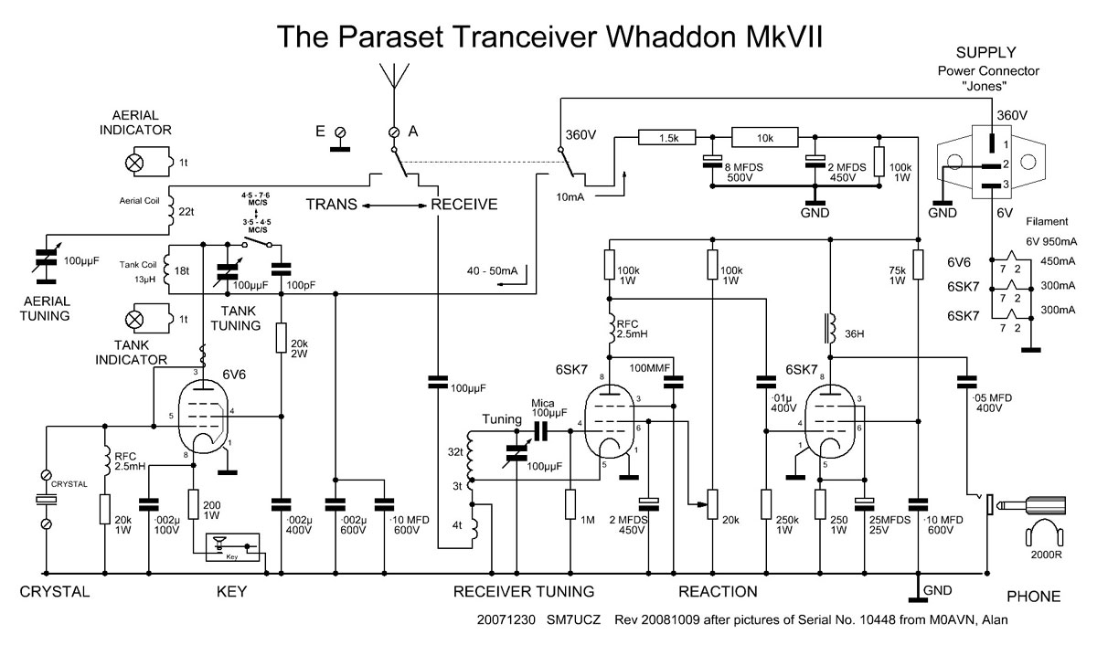
Schematic
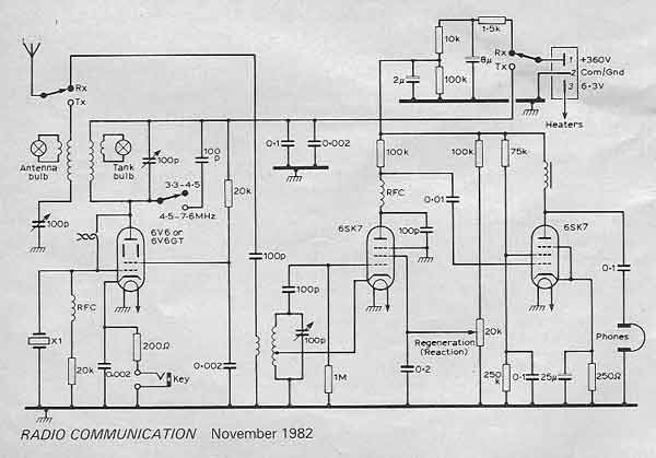
Paraset schematic from Radio Communication 1982 (pdf)
ON5LJ's drawings
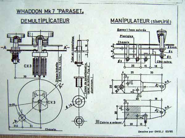


Blueprints from ON6WJ, Jos Warnier

Drawing from ON5LJ
Paraset in Norway
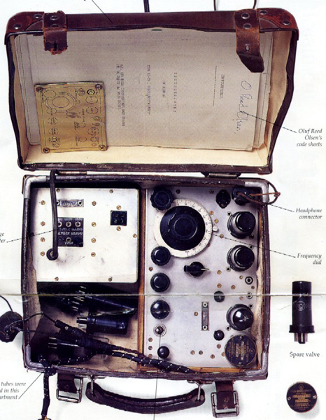
Picture of the Norweigean Oluf Reed Olsen's set. It has no screenprint. Probably an early version. And with a main power supply. Some differences were made during the war.


Two pictures from the book "På hemmelig oppdrag i Norge",1946 by Oluf Reed Olsen. Here you can see the "Cash Box" Paraset in use. Note the separate key. The first modification. And vibrator power supply.
The resistance groups were sending weather reports and positions of German shipconvoys home to England. It was a great help for England to hit the targets. The problems were the heavy batteries, who had to be charged. 26kg batteries in the backpack down to the villages for charging, was risky.
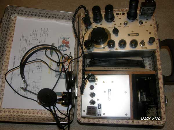
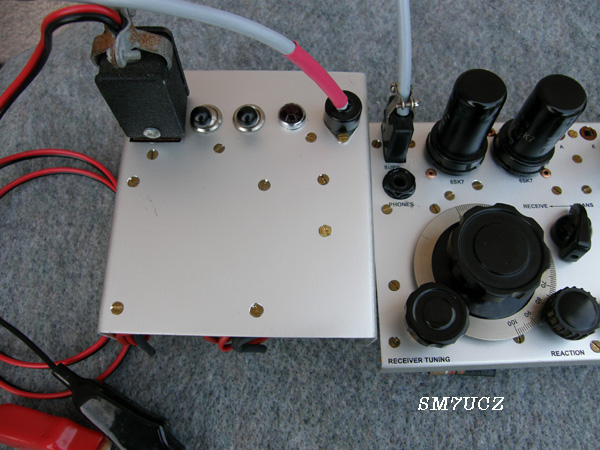
My first Paraset

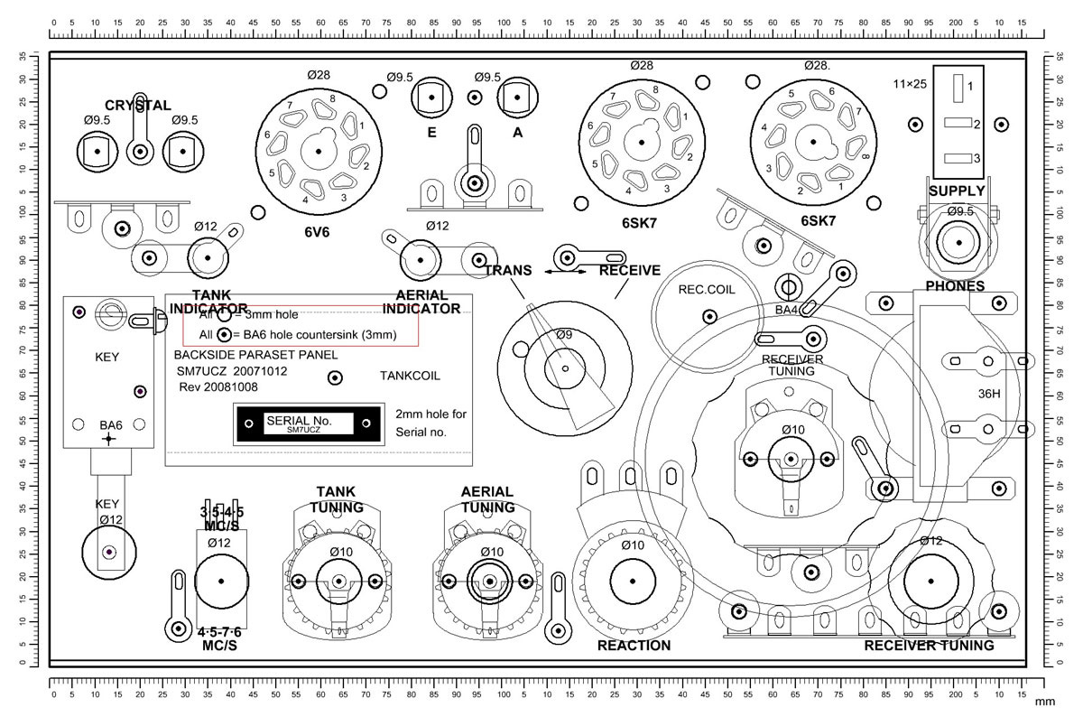
Hole makings in my first panel of zinkplate

Testpanel

Hunting for parts...

Testbuilding


Almost all frontparts
Next panel in aluminium


Schematic
Much of the fun of building the Paraset was the research of all data. Lots of that will be found on the web. For example: persones from Belgium, France, Norway, England and Italy have made big work in research..
Many drawings were found but in different shape and quality. I made new drawings after discussing all the information together with Bengt/SM7EQL, Leif/ SM7MCD, Ragnar/SM7XFZ, Urban/SM5EUF and so on....
There is conflicting information how to connect the tank coil. Should the lamp be attached at the cold or the hot side ? Tank coil shall be 38mm. I found a 40mm plastic tube. The tank condenser has to be isolated from the panel...350V on boths sides!
The 36H choke is difficult to find, but the "Jones" connectors"...are still made in USA
Paraset Replica
And how did the Paraset look? ON5LJ had made drawings from his original rig. I made new copies in CAD. Here is how ON5LJ solved it: Drawing 1 and Drawing 2
Click on pictures.... or download my latest drawing...
And you have to compromise with the parts from the junkbox...
Download my drawings
Here is a new viewer for S-PLAN 7 Viewer (2mb!!) and a new drawing, Paraset.spl7 (9mb, right click and save 20100104) so you can print all my files in scale 1:1. The drawing is made with S-PLAN7 from ABACOM costs about €40:-
I modified my Paraset with a 12V supply, keyclickfilter and side tone.
Key

The key is made of acrylic plastic. Plastic was on the market from 1933. The dimension is not perfect...
The "Cash Box"

The enclosure was made of 1 mm steelplate.
Original "Cash Box" Case
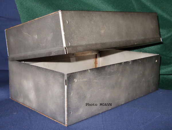
Look at the joggling from Paraset No 10448


Photo from Alan, M0AVN on a original case
Screenprint
The text has to be screenprinted on the front.

The text is printed on an overhead film in an inkjet printer on highest quality.
The rim drive

The rim drive was hard to find so I had to make one for myself. The hole is a little offside to get possibility to adjust the distance between the parts. The bearing is made from an UNF-bolt. Read more here
Valves

Real tubes from wartime.
Crystals

The crystals are of the big size direct suitable in a normal 220V outlet!!
Headset

Lot of headsets. But are they in working conditions??
POWER SUPPLY

Vibrators is rare parts today. This one was very noisy, so I opened it...
Smoketest...

Now... ready for testing....

...a mix of old and new components.
First totally silence.... one tube had open circuit...a new tube....and "Tom Jones" sung for me. Switched over for transmit... key down... some adjustment of the tank condenser and the lamps lit up. But the output differed between 2 and 5W and the audio output was a bit low. One condenser was measured to 14nF and 22 kohm at the same time...leaky! A new condenser... more punch in the audio! But the jumping power output was a loose soldereye. Power output was about 4.5W at 300V. Tested to short out thesecond grid resistor 20k ...and the output rised to 8-9W. But not so good for the tube!
Vibrator power supply from 12V battery.

The vibrator power supply with 300V stabilized voltage

A picture with key down. With a 6V6G glass tube.
2.0A at receiving and 3.2A at keydown.
QRV 2x Paraset with 2x vibrator!

First QSO with SM5EUF, Urban. We both used Paraset with vibrator pack
Missions...

Cool... Read more here
Bandspread

A 10pf variable condenser is perfect for 3500....3600kHz.
Sidetone


I like to have a sidetone so I made a test with an electronic sounder. Needed 0.28mA at 12V for sounding. A coil and a rectifier is all that is required, it sounds when sniffing a little RF.

Link to my next Paraset page
Links to others builders:
Henk van Zwam Paraset in Netherlands
VE7SL Paraset in Canada
SM7EQL Bengt Falkenberg
AE4IC Bob Kellogg
I0BR/Roberto, IK0MOZ/Mario, IK5FUZ/Alberto Paraset in Italy
Asbjørn Ursin Paraset in Norway
The Paraset Club only for members! and why??
France link and one more F6EJU France links