Spotwelding
This may be a suitable candidate for a home built in spot welding? And feed it with a standard 230V outlet? To my Paraset building needed some boxes to be spot welded. Now, I certainly profersionell help of neighbors to do the box to the transmitter. But it needed some boxes for power supply also. At a little searching online I found some home construction by point welding. It identifies the need for approximately 4V and a few hundred amperes.
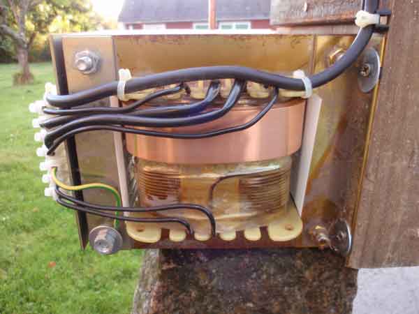
Glow Power and 300V windings removed to give a little room for the next winding.
5 turns 16mm² cable ...
Electrodes to test the transformer.
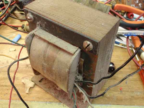
It was a miserable performance. Everything! was warm, but not the weld. The cables were really warm and soft. Cable shoes were really hot ... With a little laying on of hands may be the transformer is able to weld 0.5mm sheet metal. But the primary windings can not be dimensioned for more than 2 .. 300W. I abandoned this project. Larger transformer is needed.
Project closed
Next project
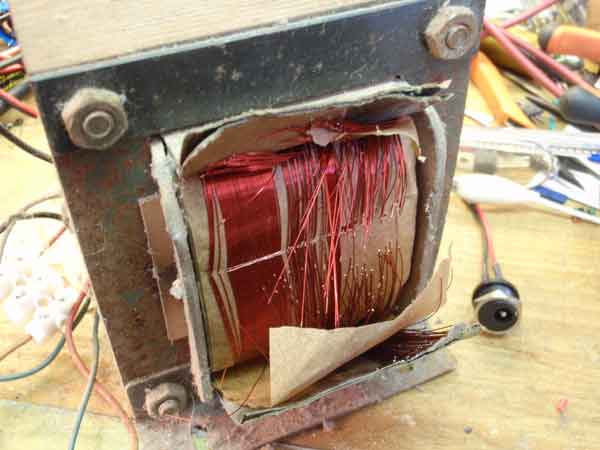
Another transformer, 1400VA, looking up in the junkbox. This transformer is designed to work from 400V to 230V in a machine to be independent of external zero. In some countries there are not loadable zero in industries. Here I drive transformer "backwards". 400V windings are not used. Unfortunately, the 230V windings extremely, so the space that was available was only 8mm wide. Where I managed to wrap the 2 x 16mm² cable with 4 turns, and so I went directly to the electrodes with their ends. Noooo... it went too badly. The cables and tools on the table, jumping around when I welded samples. It needed stronger stuff. It will not do in principle with jumper cables. After having found a "real" spot welding, so machine plate showed that it took 10kVA, also was transformer and electrodes water cooled. But this should not become a production machine, so we skip water ..
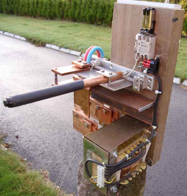
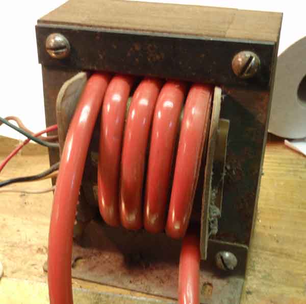
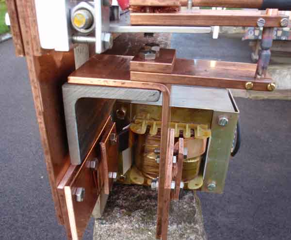
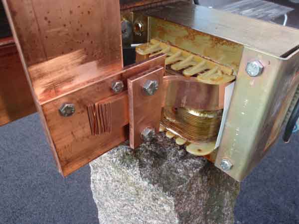
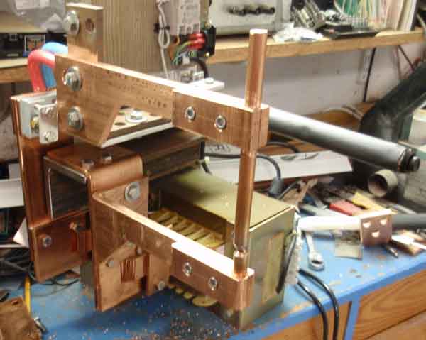
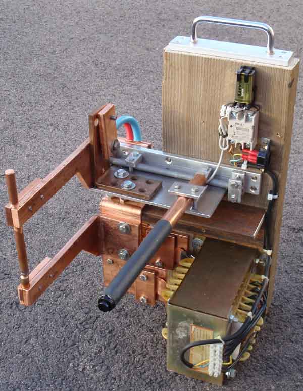
With a 2 "x 8" plank as machine frame started a new test build. Clearly this area needs up to the leaders of the transformer and the welding arms. From another scrap box mobilized 6 x 75mm² copper bars into pieces. With these started a crafts business of cutting, drilling and threading to increase the area between the electrodes and the transformer. But still, I had 4 turns of 16mm² 'starting cable "around the transformer. The result? Yes, now there were no losses in the wire to the electrodes, with the result that the transformer overload was significantly, it got dark in the basement! And even worse ... insulation on the windings around transformer began to adopt a gum-like consistency and melt together! With 8mm available space in the transformer ... what would you do? New searching the recesses ... and up came the copper strip 0.5 x 30mm. So 15mm² area. Hmmm ... 12 such flat bands could easily fit on the height, and it gives 180mm² area. But it took another handicraft work with copper strips, a new approach to the copper bin for more rails .. Now there were only opportunity with one (1) turn around transformer. May try it ...
Copper Handicraft. The hinge consists of the M12 nuts. It was the easiest and fastest to the test. Lateral displacement due to the thread moving in a hundred parts, so it will not interfere.
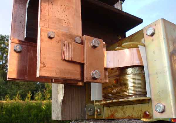
Flat bands have clamped securely.
Now, it was to weld without one was warm on the way to the electrodes. 1 turn around transformer, what does this mean?
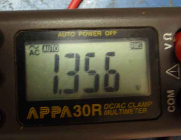
Circuit voltage of the transformer. 1.35V.
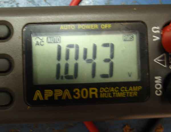
Voltage of the transformer during welding. 1 V

2200A! from the transformer under welding! That means big overload, 2200W, the transformer during the seconds that the weld duration. It was lucky I did not get there more turns around transformer.
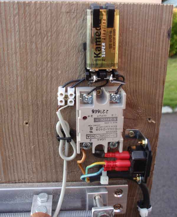
Control of the transformer is via a thyristor that can handle 40A. Trigger signal is fed from a 9V battery via the push button in the handle. Believe that it has "Zero Start" So thyristor trig, when the voltage is zero V. Then there will be no power-line surges. No flashing lights are on test.
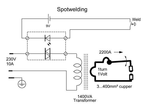
The simple circuit diagram.
Sample Welding
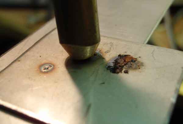
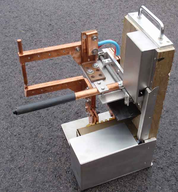
Test electrodes during construction was too thin (8mm) and the arms too short to access the inside of the boxes. New arms and electrodes was constructed. The arms of 10mm copper plates. New approach to the sponsor's copper scrap box ... 200mm long, 12mm copper rod a £3 purchased at hardware store. All processing of copper strips were in a band saw.
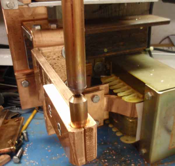
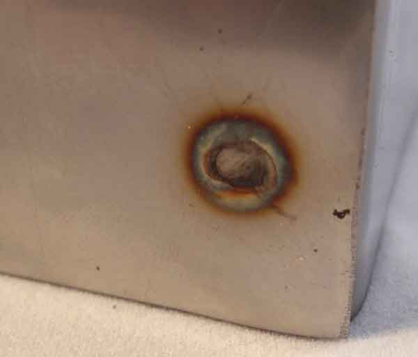
The electrodes of 12mm copper. A "real" spot welding, approximately 7mm² surface. Here it will be about 2 .. 2.5mm² surface, which is quite enough in Paraset boxes.
Testing
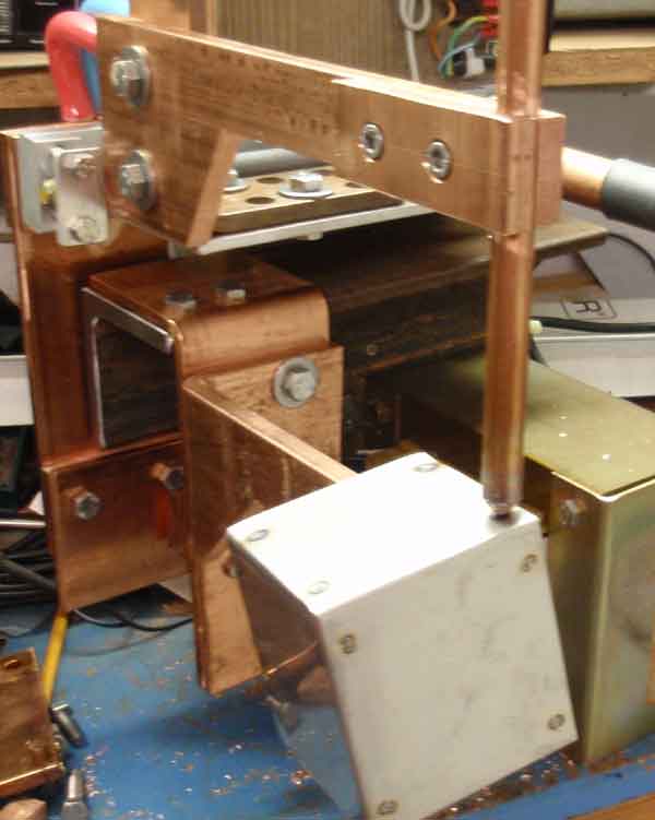
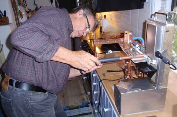
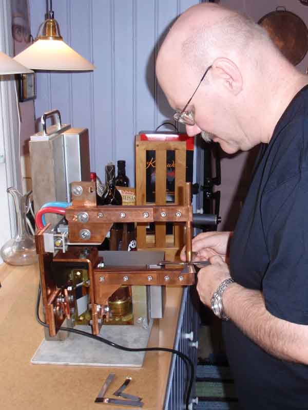
The test procedure ... And how does it then? Is it possible to spotweld with power from a standard 230V outlet? Yes, because the power is approximately 2kVA, so it can handle a maximum of about 1.5 mm plate. Have only tried with stainless steel. In addition to taking the weld slightly longer, 1 .... 3 seconds against a profi machines "knocks" at 10kW. And nothing is worrying warm ... except of course the weld. And it is just the right size to hide under the workbench. Weight? Trafo + much copper shapes and lots of bolted joints .... Appreciate it at around 30kg? Hmmm, but it weighed 42kg ... Height, 520mm.
And there are too many joints on copper strips ... but it becomes so when you build from scrap bits. Now when it is finished, I know exactly how I would have built it! Transformer straight forearms, and a copper plate rod bent into a U through transformer and directly into the arms. At each splice, I have now retrofitted more bolted joints. When there is only 1 Volt over trafo so is every mV one part per thousand in losses. And it will continue incurring losses in joints, 50 ... 100mV unless the bolt forces are properly led. Polished copper prior to assembly to reduce the resistance. Where it goes 2200A will Ohm's Law to make themselves familiar with the heat, especially where you do not want.
Normally, you use your foot to operate the upper arm and the power on. And a spring lifts up the arm. But without the foot to help it is practically on the upper arm, weighs and maintains the material in the position adjusted. Then takes hold of the handle, push down and give the power with press the button. "Real welds" has a timer that determines the welding time. Here it is for the operator to determine when it is moderate burnt.
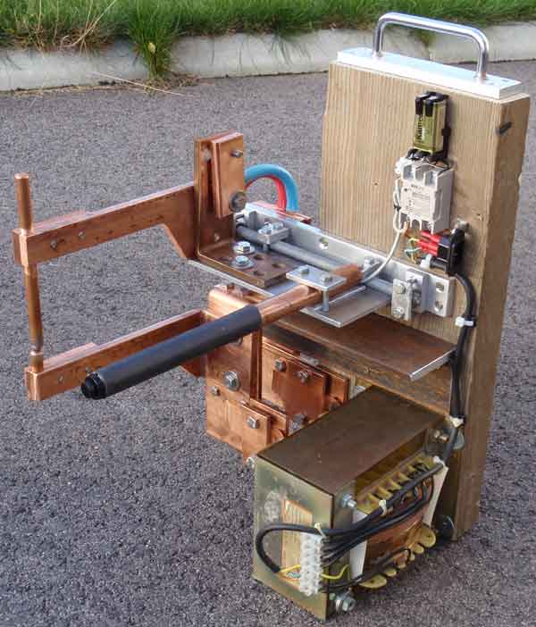
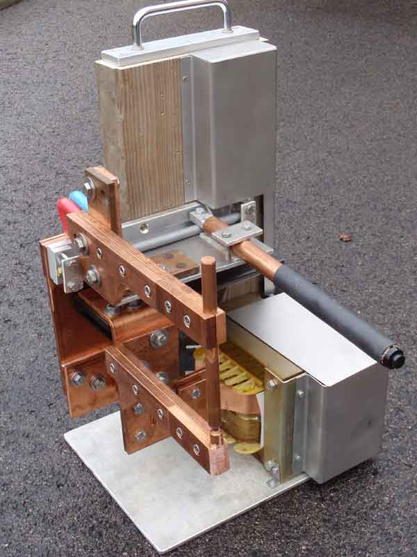
Push button for power on the handle lever.
The short piece of red / blue cable is the flexible transfer from copper to the movable upper arm.
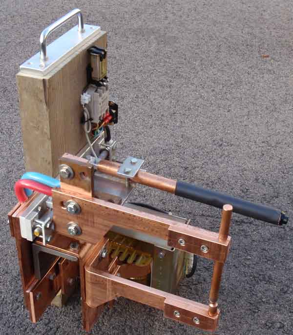
Now missing only a little protective caps and a support plate ...
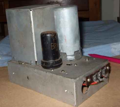
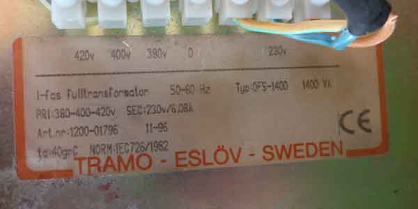
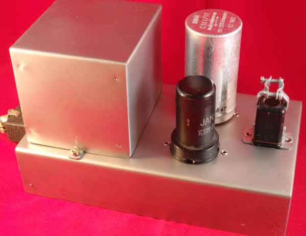
This is one of numerous types of power supply for Paraset transceiver. A vibrator transformer from 6V to 300V. This is my copy. A perfect project for the spotwelder.
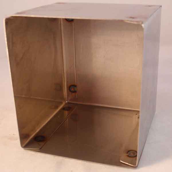
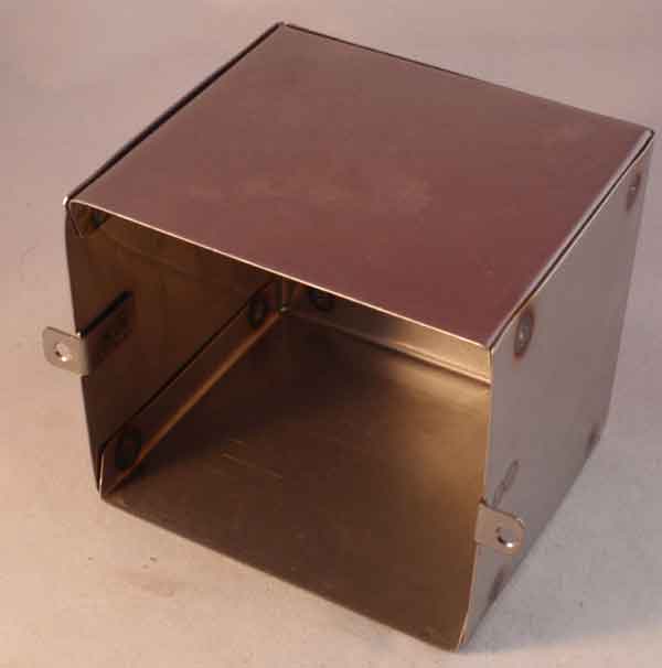
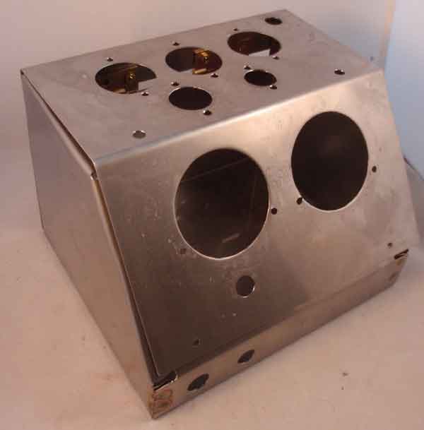
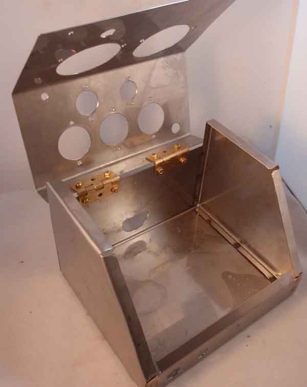
Casing to protect the transformer. This is the test procedure, both to cut, bend and spotweld.. A U-sweep + two ends in 0.5mm stainless steel in 2333.
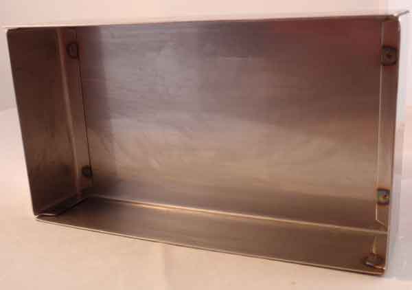
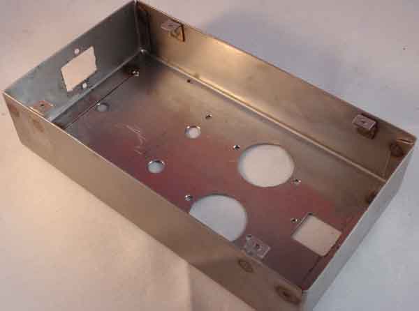
The chassis of 0.9mm stainless steel in 2333.
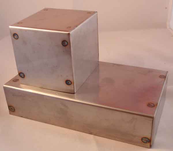
There remain some piercing yet. I will blast the entire surface to get the soft, and similar "old" chassis plate.
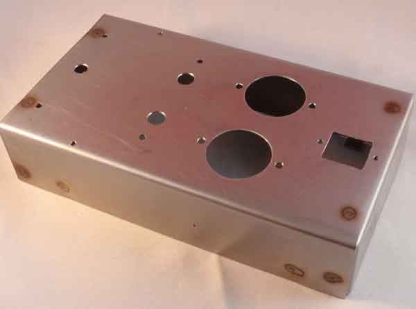
The trick for drilling in stainless ... low speed, cooling and lubricating paste and hard power.
Attach the ear of the cover plate
Ready for sandblasting ...
Ready
.jpg)
Mecanical ready
Completed
A spot welding should not be lacking in any hobby shop ....
Testpilots
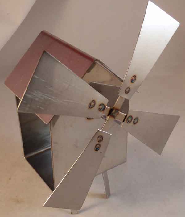
During the last "Crow Field" meeting at Tore / CBS, Öland was all participants asked to test the spotwelder by building a windmil. Trademark of Öland.
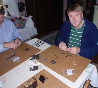
Bengt / EQL trying to piece together the parts to be fitted.
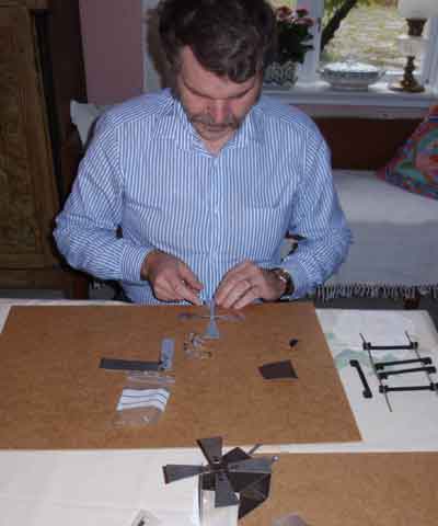
Karl-Arne/AOM has already built the wings.
Tore / CBS trying to adjust into the correct position. Tores XYL was out of town ... when we dared to be included in the warm kitchen with our exercises.
Leif / MCD welds together the wing. There are about 20 spot welds on each windmill.
Simple Tethrode tester
Chassis to a simple tethrode tube tester
Tethrode tester spot welded. See more here