Picture

Cad drawings 2000 version

Download

Paraset Box and lid.

Paraset Lid

All laser cut panels are 1mm BMS  (BRIGHT MILD STEEL)

We solder the edges of the box and lid inside. If you intend to do this (please do, it makes a better job) you must thoroughly clean and sand down the surfaces to be soldered before bending. It is easier if you do this now before bending.

These, with patience can be folded using just a vice and hammer. Make sure the surface of the hammer is unblemished (file and sand it down if you have to) so the metal is not damaged during chassis bashing activities. Form each bend a little at a time, until complete.

IMPORTANT. Fold the front and back sides of both box and lid FIRST.......before you fold the ends. This to MAKE SURE that the ends overlap the front and back sides and do not tuck in-between them. If you tuck the ends in....... the box will be too short to take the chassis. The situation is recoverable but you will have a lot of filing to do to make the chassis fit.

Coarse emery cloth will remove any blemishes caused by the bending process.

Paraset Box

The Paraset Chassis.

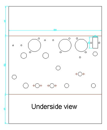
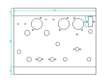
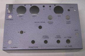
The chassis has most holes cut in it ready for you to use.

Because we do not know which type of variable capacitors you are using, the main hole will be cut, so one type of variable can be fitted directly. If you use the type of variable that has two small mounting screws we have made the laser etch-mark the position of the two holes ready for you to drill. CHECK these markings are far enough apart to fit your intended capacitor before you drill these holes!

The laser will cut a hole for the key knob, but not any mounting holes for your intended key. You must mark and drill these if they are needed. The hole for the key knob also fits the standard 1/4" jack socket if you want to put one of these in for plugging in an external key.

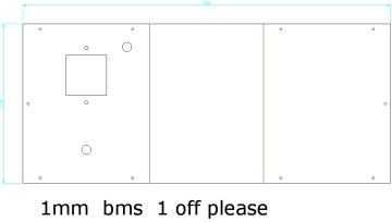
You must mark and drill a hole to mount your chosen receiver coil and also the hole to mount your pa coil assembly.

If you make a mistake and drill a hole incorrectly, don't worry, counter sink the hole and then using a hot soldering iron solder over and into the countersink. Once excess solder is sanded down you won't see where the hole was!!

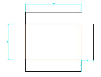
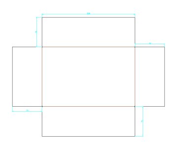
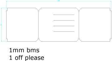
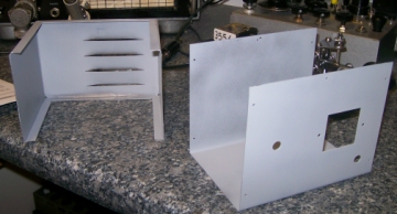
IMPORTANT. When you come to bend the chassis make sure you bend it the right way up. The laser will etch-mark where the bend should be but it is up to you to make sure you don't bend the chassis inside out! Look at the photos and make sure you will bend it correctly!

The Paraset originally came in a wooden box, and the chassis sides were not very deep. If you intend to make the wooden box version then this chassis is for you! To countersink holes in aluminium do buy the proper countersink drill....... as the finish and ease of countersinking is well worth the couple of pounds or so for this special drill.

In 2mm thickness the aluminium chassis is easy to bend and countersink. The holes in the sides for mounting the chassis inside the box are missing deliberately as you drill these to match the holes in the sides of your box....using the box holes as a template to mark out of course.

This picture shows the bent chassis, painted and labels done ready for construction.

NOTE: HF TUNING and LF TUNING are words not normally found on a Paraset. This particular Paraset is being bandspread so it covers 160m and 80m hence the wording of the switch here. Normally this switch is marked with the two tuning ranges covered by the Paraset. The rub down lettering used here is 12 point Helvetica Medium 3mm.

Paraset Lid Strap

Clean this thoroughly before bending as it is to be soldered to the lid.

This strap is longer than required and you must cut it to length after bending.

It is used to form a lip around the two sides and front of the lid (not the back where you fit the hinges) and allows the lid to close and stop on top of the box holding the Paraset chassis. Bend it in a vice and cut off the excess after bending. This strap has to be soldered to the lid holding it in place, so don't forget to clean the edge of the lid as well so that the solder takes properly.

Power Supply

Power supply bottom
Power supply cover.
If you look at the pictures of the top and bottom you will see the top fits inside the bottom and is located by self tapping screws. The large cut out is for the mains tap adjustment panel if you can find or make one to fit here. We fit crystal sockets to this panel and inside the unit build a small transistor crystal oscillator which is used for netting. Without this facility the paraset is nearly impossible to use.

Note 1: The metal work is laser cut with four slots for the louvres in the top to be formed outwards. It is just a simple matter to "raise" the louvres with a piece of curved wood dowell and using a hammer "tap" them out.

Note 2: Bends are easily formed in a vice using blocks of wood and a hammer. However spare a thought as to which bends you form first or you could "box" yourself into a tight spot!!